As you open up the node properties there are a few types of operations you can use. Amongst the most commonly used, such as over, stencil, screen, divide/multiply, there are a bunch that aren’t used as often. At times you’d even have to ask yourself whether or not you’ve used the operation at all. Thoughts and questions aside my purpose is to dive into these topics in depth, backing up with links, reads and some papers to check out.
- History of the merge node
- Importance of the alpha channel
- About the algebra of compositing operations
- Application case studies
History of the merge node
Firstly, let’s talk about why there are so many operations. The whole premise was to create a node that had correct mathematical operations to combine elements that were rendered separately form each other. Why? Very simple – at the time (and to this day, to be quite honest) it was an extensive and expensive process for a single program to render the entire scene. Not only it was quicker to break down the scene into much smaller elements, but also a considerate action to minimise the repercussions of changes in the scene due to small errors. Then these elements could get combined later, at the compositing stage. However, when merging these elements we always have to think about anti-aliased accumulation of the full image.
Anti-aliasing – a word that typically refers to a number of techniques that are used to combat aliasing in a sampled signal such as digital image or digital audio recording.
Aliasing – visible distortion caused when a continuous line or transition is not smoothly captured, due to low resolution or sampling rate of a digital medium. In simple words it’s a jagged edge of an object in an image.
For the rest of the post, when we’re talking about an element we are specifically talking about an image that has 4 channels: the classic red, green and blue (RGB), and alpha channel, containing the associated matte of the rendered object. The methodology used to composite the images should not be introducing aliasing. We are thinking about preservation of the soft edges, without introducing any artefacts.
Importance of the alpha channel
It is necessary for existence of a separate component to contain the matte information of an object. It tells you the extent of a coverage of an element at a pixel. If you’re trying to affect the opacity – it’s all about manipulating your alpha channel, not the colour information in RGB.
If you’re trying to affect the opacity of an element – it’s all about manipulating your alpha channel.
The computer needs this information as it is using some kind of interpolation between the object A (e.g. foreground/FG) and object B (e.g. background/BG) colours when mixing together. This cannot be done as part of colour information. So, as alpha channel gets introduced, it has few simple conditions applied:
I) Alpha = 0 means no coverage (non-opaque / transparent)
II) Alpha = 1 means full coverage (opaque / non-transparent)
III) Fractions correspond to partial coverage.

If you go back to the Thomas Porter and Tom Duff paper they mention about importance of pre-multiplied image undergoing the merge operation. So remember, when we combine our images they already have to be pre-multiplied. To my understanding, it’s to do with the simple fact of using one operation less (aka the multiplication of the colour channel by the alpha channel) when combining the elements.


About the algebra of compositing operations
Small foreword: I do love exploring and trying to understand the maths behind all operations in nuke, but I know that it can be daunting and frustrating to go through these texts when you’re doing quick research yourself. So I’ll try to make this more structured and give you the choice of whether diving deep with me, or jumping straight to application study cases stage.
Assumptions:
- A complete background (BG) image has an alpha of 1 everywhere: noted as
at every pixel.
- Any matte that is a colourless shape used for controlling the compositing of elements (aka a mask) has 0 in all the RGB values, and alpha values between and including 0 and 1:
.
Say, we have two semi-transparent objects A and B; image A with alpha, 

- At a given pixel each object lets
of the BG colour through (as the object itself gives an
of it’s own colour). So for the two objects A and B, at the pixel in their combination area they will allow
of BG colour through.
- We then say that
portion of the background colour is blocked by A and passed by object B.
- Similarly,
portion of the background is blocked by B and passed by A.
- Hence,
of a pixel is blocked by both objects A and B.
Now, for two opaque geometric objects A and B, the overlap within the pixel is quite straightforward:
- We see
of the BG (aka 100% of A and 0% of BG colour, since opaque implies
).
- Similarly object B divides the pixel into two subpixel areas of ratio:
.
This all may sound and read confusing, so I’ll go the visual route with some simple maths. Remember Venn diagrams from school? Well, let’s think of it this way – when we are combining 2 images there are 4 parts to consider: the BG or nothingness, image A, image B and the overlap of images A and B.
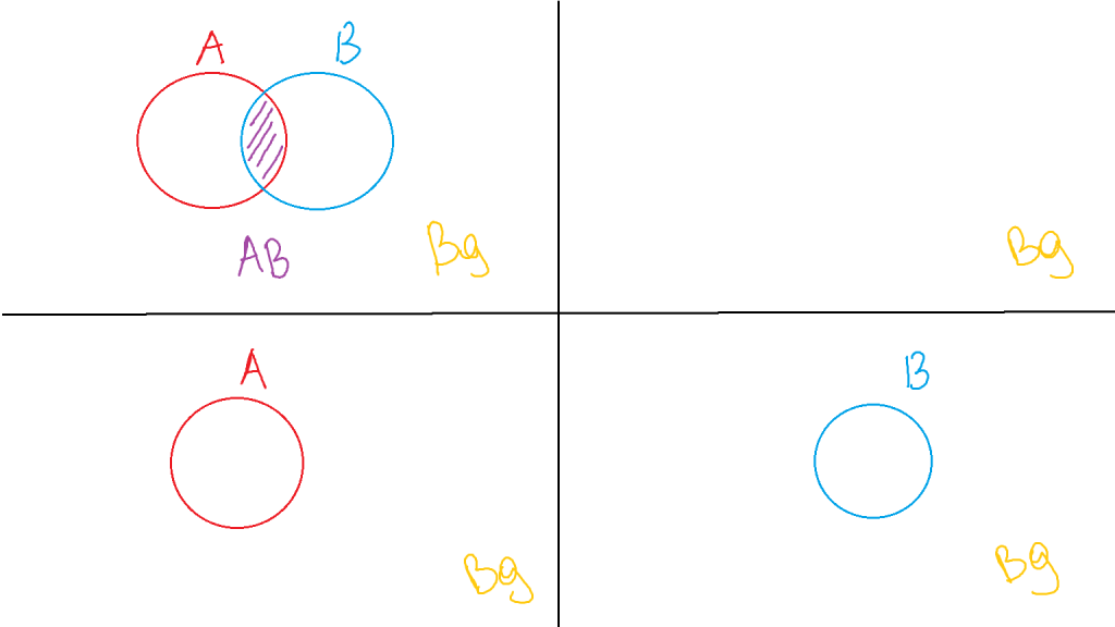
So in every operation we can mark whenever any of the four sections (or, subpixel areas, as mentioned in the paper) will be part of the final image: 0, A, B and AB overlap.
Clear – clean Venn diagram – 0,0,0,0
A – A circle – 0,A,0,A
B – B circle – 0,0,B,B
So far this is straightforward. We can see whole A or B, so they take up 100% of what they are.
Now, the simple combination of those:
OVER
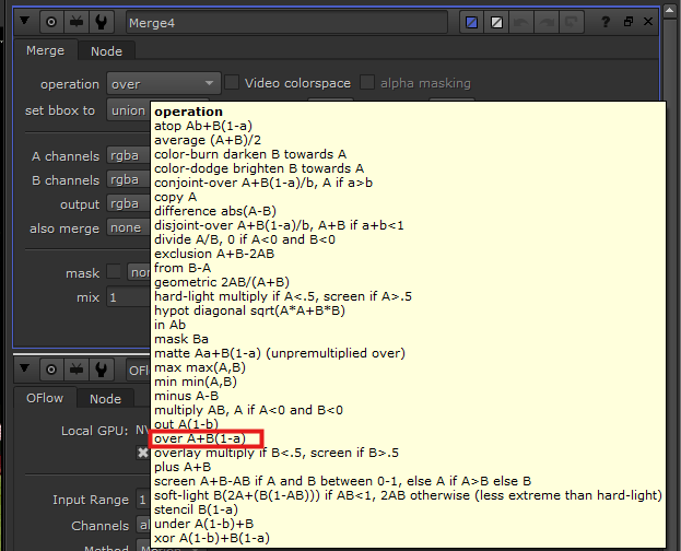
A over B – A circle, part of B circle, the rest of B circle that is occluded by A – 0, A, B, A
We see 1 part of A for A area, we see 
That is why when hovering the operation menu for merge, for “over” you see A + B(1-a), where upper case letters represents the objects RGB values and lower case represents the according objects alpha.
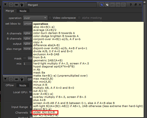
The opposite of over is operation “under”.
A under B – B circle, part A circle – 0,A,B,B
We see 1 part of B for B area, we see 
IN (inside of)
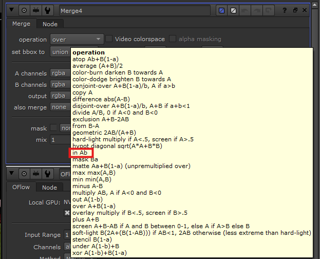
A in B – A part that is inside of B, in merge node known as “in” – 0,0,0,A
So we see

B in A – part of B that is inside of shape A, in merge node known as “mask” – 0,0,0,B
We see
OUT (outside of)
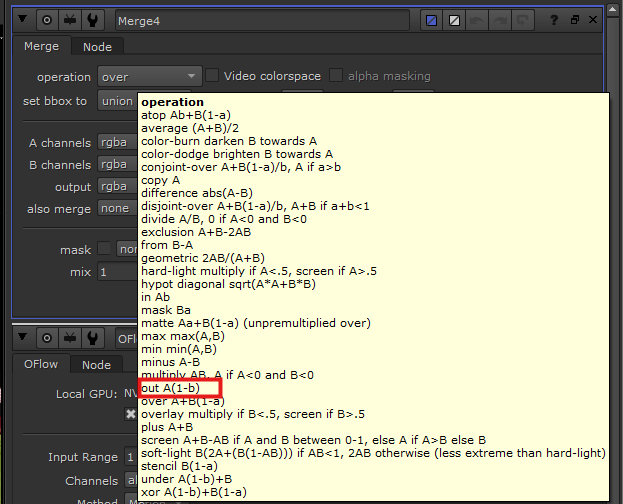
A out B – A part that is outside of B, in merge node known as “out” – 0,A,0,0
So we see
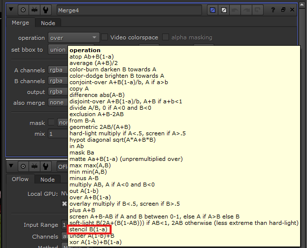
B in A – part of B that is inside of shape A, in merge node known as “stencil” – 0,0,B,0
We see
ATOP and XOR
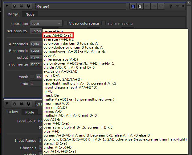
A atop B – We see B and the part of A that is overlapping B – 0,0,B,A
So we see

A xor B – We see
The whole reason we wanted to find the fractions (
PLUS
A plus B is quite straightforward where the images both survive in their areas and in the overlapping area they get summed together. Mathematically speaking that would be A+B, values of A in RGB and of B summed together. Note, that in such a case the values can easily go beyond 1 and you have to keep that in mind.
Application case studies
One thing is to understand the logic behind combining a bunch of pictures, another is to put it to practice. I won’t go over a lot of cases, as there are still many that I haven’t come across, however I will point out to most common ones I used so far and ones I’ve learnt to look out for.
To clarify, mathematically speaking, the operations will be affecting both alpha and RGB colours of the composite image (and can affect other layers and their according channels, if you choose to do so). Keeping that in mind, in the following table when I name the columns of what you’re affecting, it’s more driven by what you wanted to do with the 2 images when merging together.
| To affect the RGBs of the composite | To affect mattes |
|---|---|
| Over / under – placing image A either on top or under the image B. | Over / under – merging the matte of the composites together. |
| Disjoint-over – It is useful when you have two objects overlap, and one of them either has already been held-out during rendering stage or undergoes a comp where it’s being held out by another object, before they merged together. At the stage of merging together, you’d choose disjoint-over because if you were to choose over, it would produce dark lines around the comped objects, since the operation over is already doing held out of the background object. In this case it would get held out twice. (Very good if you don’t want to have any problems at tech check stage) | Disjoint-over – Same as in other column. |
| Mask / in / out / stencil. | Mask / in / out / stencil. Those are more often used as an operation to affect the matte, allowing you to change the area seen of the final composite. |
| Plus – often used to adding sources of very bright light, such as laser beams, fire, sun beams, hot spots. | Plus – Better not to use that to combine mattes as it will provide numbers bigger than 1 for alpha channel which is something you don’t want to have. |
| Screen – a good one when you’re adding reflection or laser beams on top of your comp. | Screen – good way to mix the mattes of two images. |
| Max – useful to bring aspects like bright hair detail through. | Max / min – good way to combine mattes. |
| Hypot – useful to add reflections, as an alternative to screen. | |
| Difference – at the stage of tech check you want to make sure that you’re only affecting the areas you needed to and nothing else. You’d plug in the plate and final comp images and check the areas of where you see the difference corresponding to the areas you were supposed to affect. |
I hope this made you understand merge node better, and provided with some clarification as to in which cases you’d apply which operation. Two operations I will do a separate post on and their case studies are multiply and divide, as I found them to be incredibly useful beacuse of the simple maths operations working the best in a few case scenarios.
https://learn.foundry.com/nuke/content/comp_environment/merging/merge_operations.html – Wonderful table by found which both gives you image visuals for all operations and names examples of application of an operation.
